


Chlorine Solution Diffusers
Couldn't load pickup availability
Introduction
Potable Water vs Wastewater Treatment
Emphasis on adequate mixing is usually greater in wastewater chlorination than for potable water. This is largely due to the fact that wastewater chlorine dosages are 5-8 times those for potable water However it should be pointed out that the diffusers C-265, C-266 and C-267 for pipes flowing full are specifically designed to provide a properly mixed sample in the least amount of lag time for residual control purposes in water supply conduits.
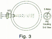
It should also be pointed out that while the open channel diffusers C-365 and C-367 are used primarily in wastewater for efficient disinfection, diffuser C-266 (Fig. 3) is the most satisfactory diffuser for treating raw sewage for odor control. This diffuser can be installed in those cases so that there will be a negligible amount of obstruction to the sewage flow.
The design concept details of these diffusers are fully described in the Handbook of Chlorination Second Ed. by Geo. Clifford White. Van Nostrand Reinhold New York, NY 1986. See Chapter 8 pages 539, 540, 544-551; Chapter 9 pages 662-664 and Appendix pages 1031-1033.
Diffusers as Mixers
In the early years of chlorination, diffusers were designed primarily to carry and inject a corrosive chlorine solution to the point of application. However in recent years with extensive use of chlorine for wastewater disinfection it has been demonstrated that diffusers can be designed to perform as a satisfactory mixing device. This is true for both closed conduits and open channels. With this in mind, diffusers furnished by Chlorine Specialties are designed to provide maximum mixing performance based upon more than twenty years experience. It should be pointed out however that local conditions involving hydraulic transients are the responsibility of the design engineer and are beyond our control.
Hydraulic Design Considerations
All CL2S jet diffusers, both the closed conduit and open channel types, are designed to produce a jet velocity of 23-26 ft/sec. This results in a d iff user head loss of about 10 ft of water. The C-265 is not a jet type diffuser. It is used where pipes flowing full up to and including 24 inches in diameter.
Materials of Construction
All of these custom made diffusers are made entirely of PVC, The fittings are heavy socket weld and the pipe is schedule 80 PVC.
C-266 and C-267
C-266 and C-267
These diffusers are for pipes larger than 24 in. They are the new Egan Jet type diffuser, designed to propel the chlorine solution at a velocity of 23-26 ft/sec.
 C-266
C-266
The C-266 diffuser (Fig. 3) discharges the chlorine solution across the diameter of the pipe. At this velocity the chlorine solution will easily traverse the diameter of a 36 in. pipe.
This across the pipe jet action will insure a thorough mix of the chlorine solution at 10 pipe diameters downstream from the injection point.
Ordering Procedure—C-266
Providing the same information as for the C-265 diffusor plus the following:
- Injector water flow—max. gpm
- Injector Size: (1" fixed throat or 2f 3," or 4" adjustable throat)
 C-267
C-267
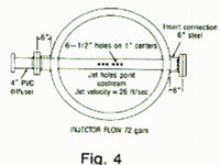
This diffuser shown in Fig. 4 is lor pipes larger than 36 inches but can be used for smaller pipes. Similarly, the jet velocity of this diffuser will be 23-26 ft/sec but in this case the diffuser must be installed with the jets directed upstream counter to the pipeline flow. This arrangement insures a thorough mix ten pipe diameters downstream for the injection point.
Ordering Procedure for C-267
Please Provide the Following
- Pipe Diameter
- Pipe wall thickness
- Materials of construction: steel or concrete
- Injector water flow—max gpm
- Injector size
Open Channel Diffusers—C-365 and C-366
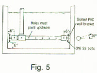
These jet diffusers are also designed to produce a chlorine solu¬tion velocity of 23-26 ft/sec. They should always be installed with the holes pointed upstream to achieve maximum mixing efficiency.
 C-365
C-365
This single pass across the channel diffuser shown in Fig. 5 is designed to be lowered into wall brackets. Operating evidence indi¬cates that this type of diffuser should be limited to channels carry¬ing less than 10 mgd or those wider than 5 ft. Beyond these limits there is a significant decrease in mixing efficiency. Therefore in these instances the diffuser should be supplemented by a mechan¬ical mixer immediately downstream from the diffuser. Holes must point upstream.
Ordering Procedure C-365
To order a C-365 diffuser by code number, three numbers are involved. The first number is the pipe size; the second number is the distance between the supporting sides of the channel in inches; the third number is the expected maximum chlorine solu¬tion flow in gpm. The riser will be kept to one extreme end as shown in Fig, 5. The perforations will be on one side of the pipe at the angle shown in Fig. 5. Therefore, the code number of a 2" C-365 diffuser for a 4' channel and 45 gpm of chlorine solution would be C-365 (2 x 48 x 45).
 C-366
C-366
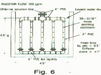
For channels too large for the single pass C-365 diffuser, the multiple pass diffuser C-366 can be designed to provide adequate mixing without the need for a mechanical mixer.
A typical multiple pass diffuser is illustrated in Fig. 6. Here again the holes should be pointed upstream. Properly designed, these diffusers can generate a Velocity Gradient factor G = 500+.
Ordering Procedure—C-366
The following information is needed to design a custom made C-366 diffuser.
- Channel dimensions
- Peak daily dry weather channel flow
- Height above bottom of channel to lowest operating water level (LWL), see Fig. 6.
- Maximum expected CL2 or S02 feed rate lb/day
- Injector size (1 inch fixed throat, 2 in., 3 in., or 4 in.)
Pipeline Diffusers Series 265, 266 and 267

These diffusers are designed for closed conduits flowing full. There are three types depending upon the diameter of the pipe.
C-265
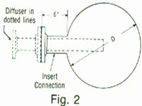
This diffuser is for pipes up to and includ¬ing 24 inches in diameter (see Fig. 2). It is designed to inject the chlorine solution into the center of the pipe. This will result in a complete mix of process flow and chlorine solution 10 pipe diameters downstream from the diffuser provided the pipeline flow is sufficient to generate a Reynolds Number (NR) of 3000 or greater.
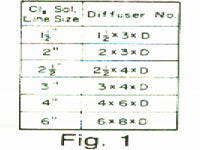
Ordering Procedure for C-265

To order a C-265 pipeline ffiffuser three numbers are involved. (See Table Fig. 1). The first number represents the chlorine solu¬tion pipe size. The second number represents the insert pipe size, The third number represents the pipeline diameter in inches. The two flanges of the diffuser always retain the same relationship to each other and this is the basis of our code numbering system. The user must, however, furnish the flanged insert connection on the pipeline to the dimension shown in Fig. 2 and with a flange that matches the inner flange of the diffuser. For example, the code number of a 2" C-265 diffuser for a 12" pipe is C-265. (2 x 3 x 12). This means the insert is a 3" pipe with a class 150 flange- The inner flange on the C-265 will match this flange while the outer flange is for 2" pipe, All C-265 diffusers are designed to penetrate to the center of the pipeline.